Master’s Thesis
Leveraging Generative Design in Design for Additive Manufacturing (DfAM)
I made this with two other friends in Robotics Club at my sixth form. This was a fun side project that I did alongside my first year of A-levels.
We wanted to make something out of the spare pieces and materials that were lying around in the Computing and DT departments.
In the end it was massively successful. It was good enough for playing a large variety of games, and proved very popular around the school.
The idea began in January 2015 when I was in Robotics Club with two friends trying to come up with a fun project to do.
We had the following materials at our disposal:
Making an arcade machine out of these parts was an obvious choice. We also chose this because it was a popular Raspberry Pi project so there was lots of information online to help us if we needed.
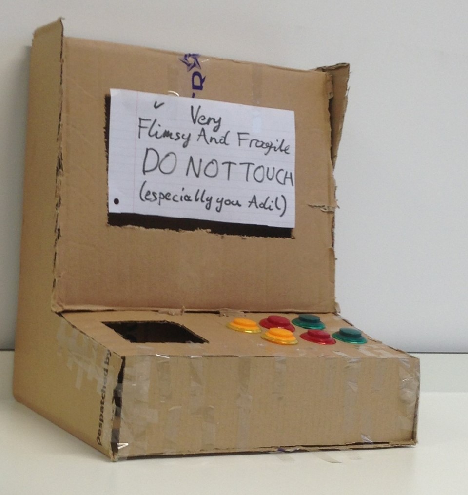
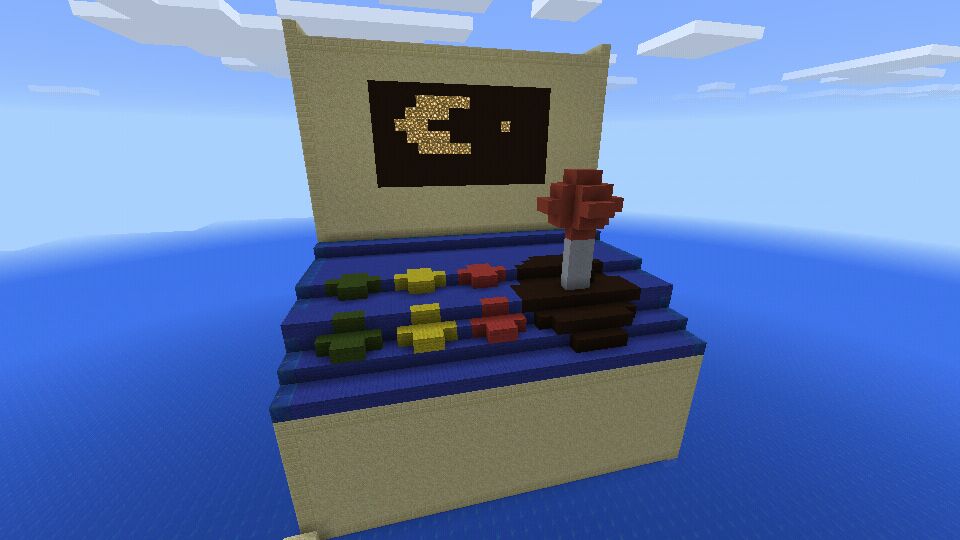
To get an idea of proportions and dimensions, we mocked up a model out of cardboard and tape.
We used our school’s DT department to assemble the enclosure. We found some spare sheets of 5mm thick MDF in a scrap pile to use.
We made a schematic of the enclosure composed of five panel pieces. They all join together using PVA glue and finger joints.
Schematic of enclosure panels?
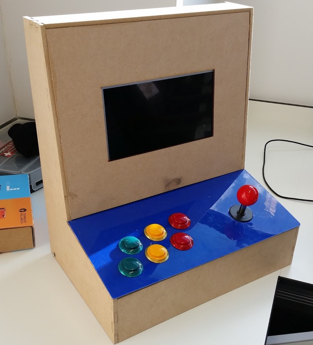
We covered the top of the controls panel with blue acrylic. The holes for the buttons and joystick were CNC laser cut.
The rear had a sliding polystyrene board, which provided easy access to the internals.
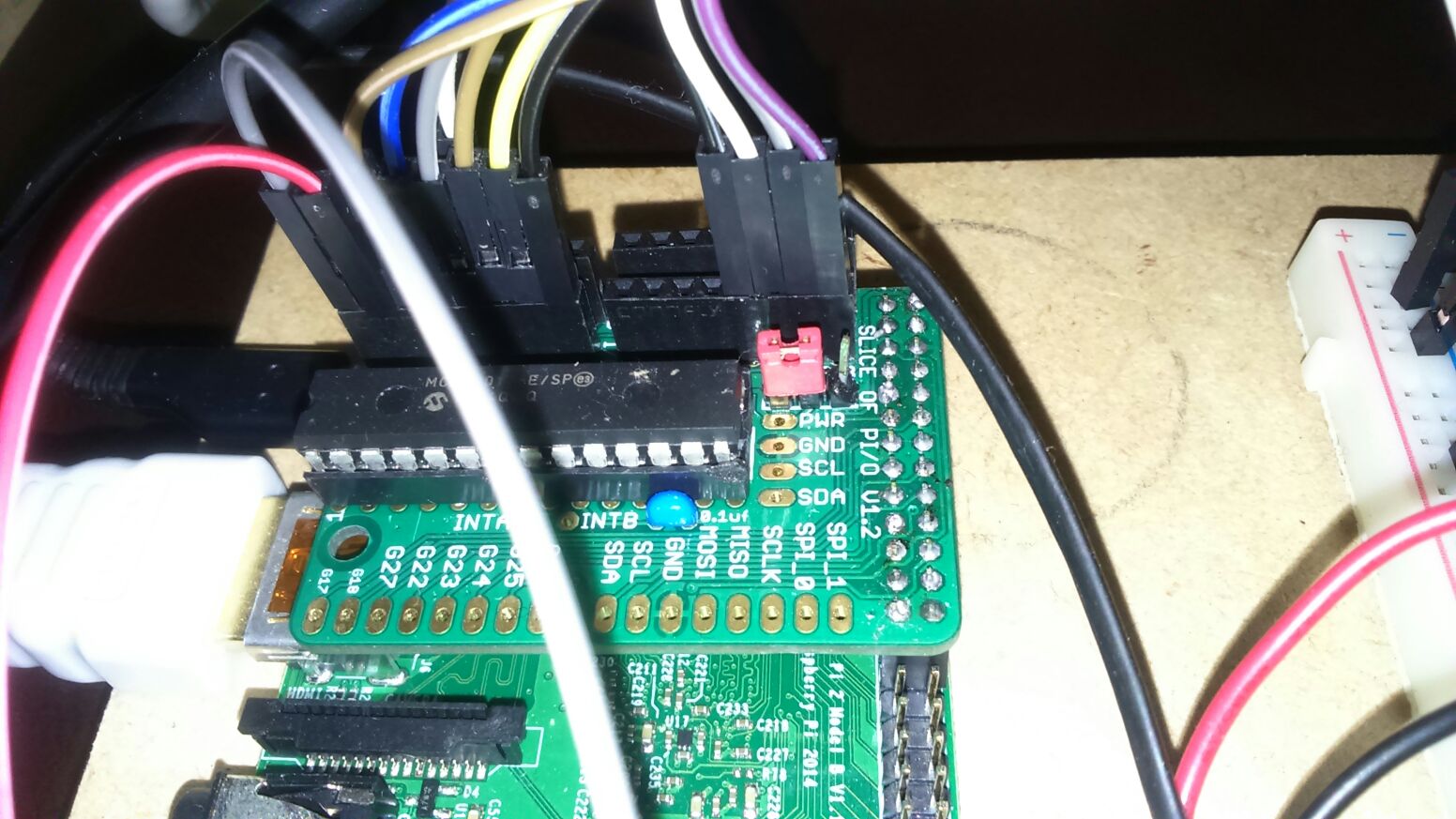
The arcade machine is composed of six buttons, and a joystick with four microswitches for up, down, left, right. This meant that ten digital input pins were needed.
This also meant that ten pull-down resistors were needed. Thankfully, the chip used for the GPIO expander was the MCP23017, which has configurable pull-down resistors built in.
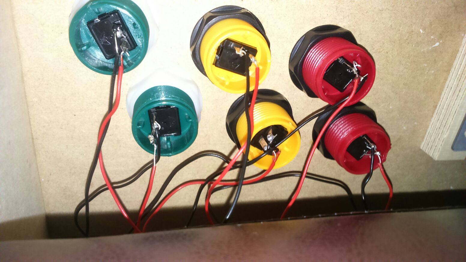
Connecting these together was very simple. Single core wires were soldered to the buttons and joystick, which were connected to a breadboard and connected to the Raspberry Pi via jumper cables. We felt this was the best compromise between upgradeability and robustness.
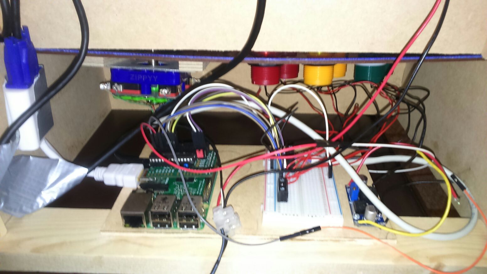

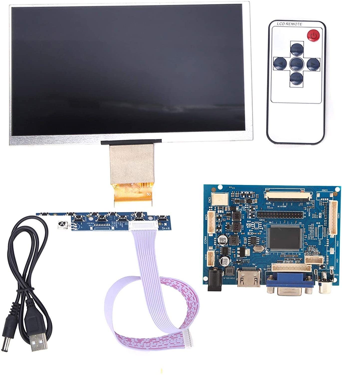
The screen was a 7” 800 x 480 pixel LCD panel bought off of eBay. It came with its own controller board, which accepted a variety of video inputs including VGA, HDMI, and composite video. Connecting this to the Pi was easy as only an HDMI cable was needed.
Much of the time taken on software development was spent on trying to get the buttons and joystick to work.
We used a version of the Raspbian linux distro that came with RetroPie installed. RetroPie is a software project that makes it easy to play retro games on a Raspberry Pi through a set of emulators.

When the system starts up, the user is presented with a menu for a range of game systems. Once selected, the user can choose from a range of games for that system.
When the user launches a game, RetroPie automatically launches the relevant emulator and configures the controls. It also returns gracefully to the game selection menus when the player quits a game.
Screenshots of menus?
Games are added by copying game ROM files to a directory in the system. In addition to a few game ROMs, I also added some games that I developed in Python.
On the first power on of the completed product, the system booted successfully into the EmulationStation menu. However, the controls did not function at all.
This lead to a lot of trial and error debugging. I tried a wide range of things, including recompiling the driver, editing its source code, changing the Raspberry Pi and the MCP chip, using different wires etc.
In the end, I found that the Pi couldn’t talk properly to the MCP chip because the I2C bus speed was set too fast. Finding this out was extremely frustrating and only came about after over two months of persistent debugging.
Once found, this problem was quickly solved by modifying a single variable in the driver.
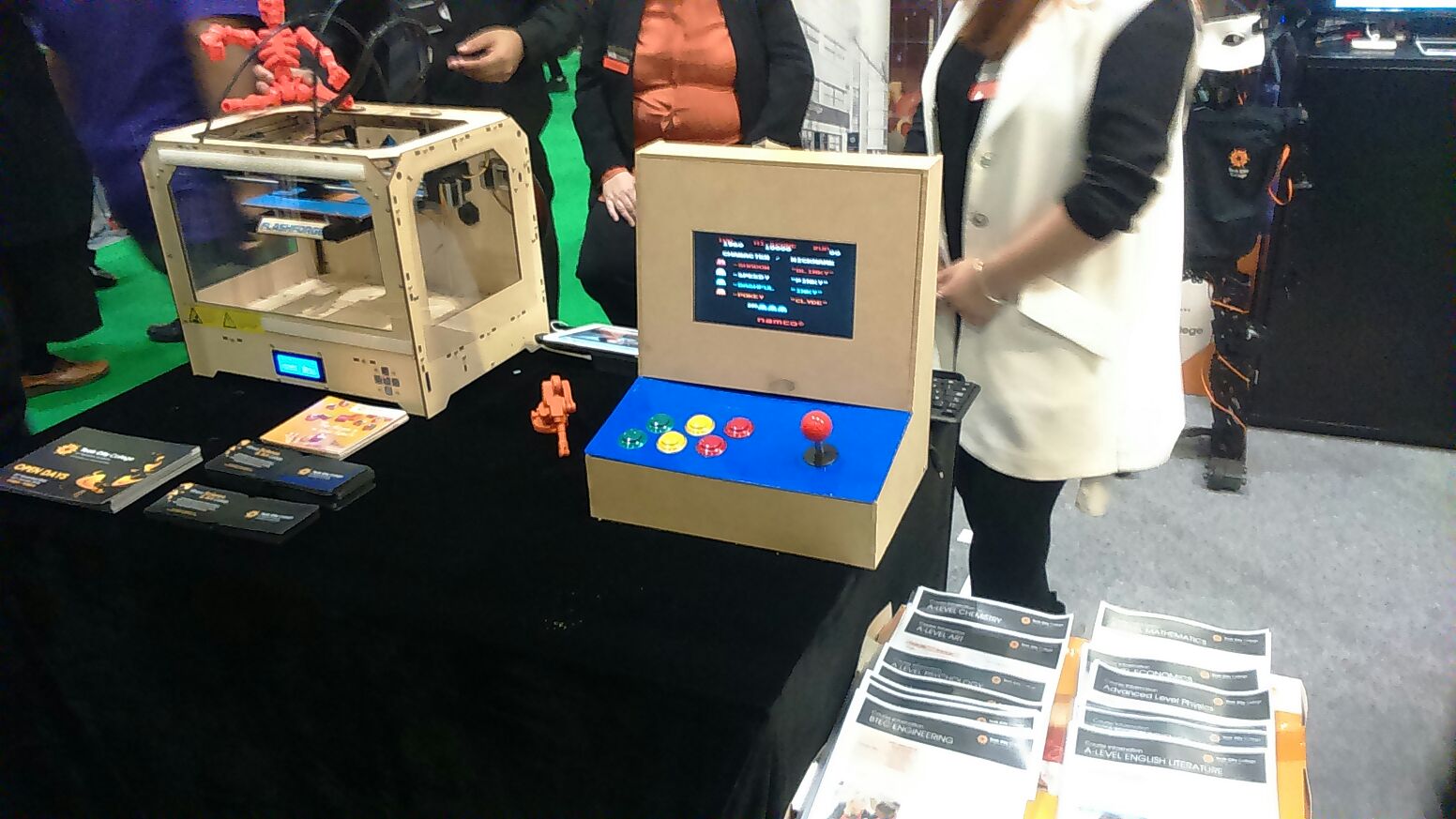
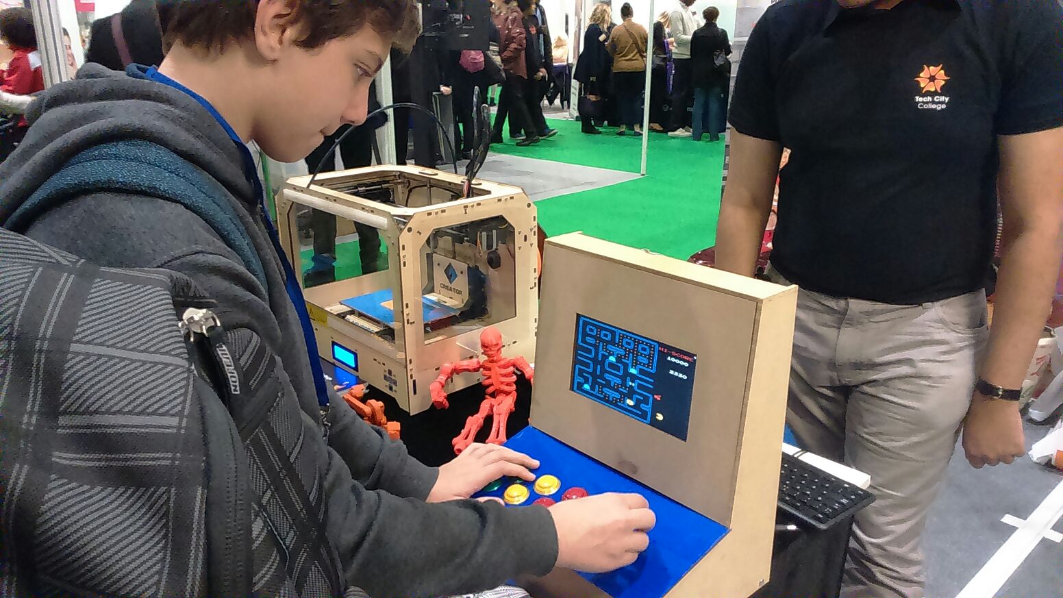
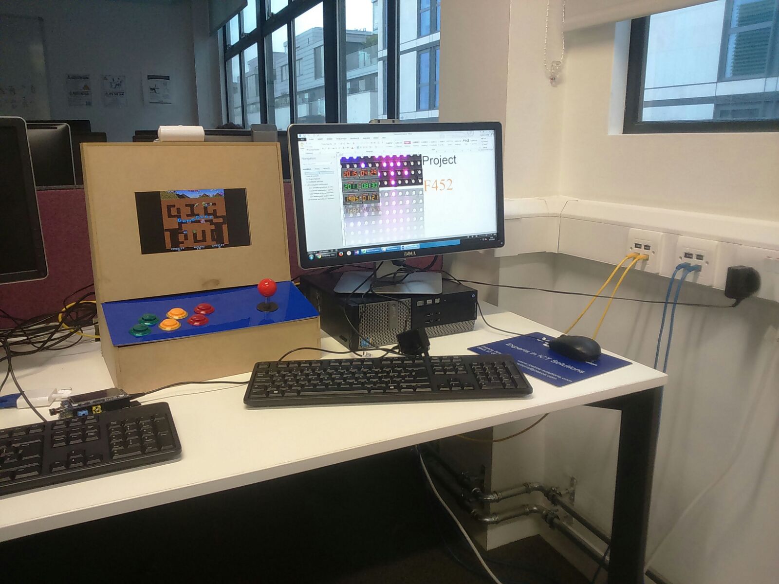
Playing a range of games on the arcade machine was a pleasant experience. The controls were very responsive and the system could run nearly all relevant games at full speed.
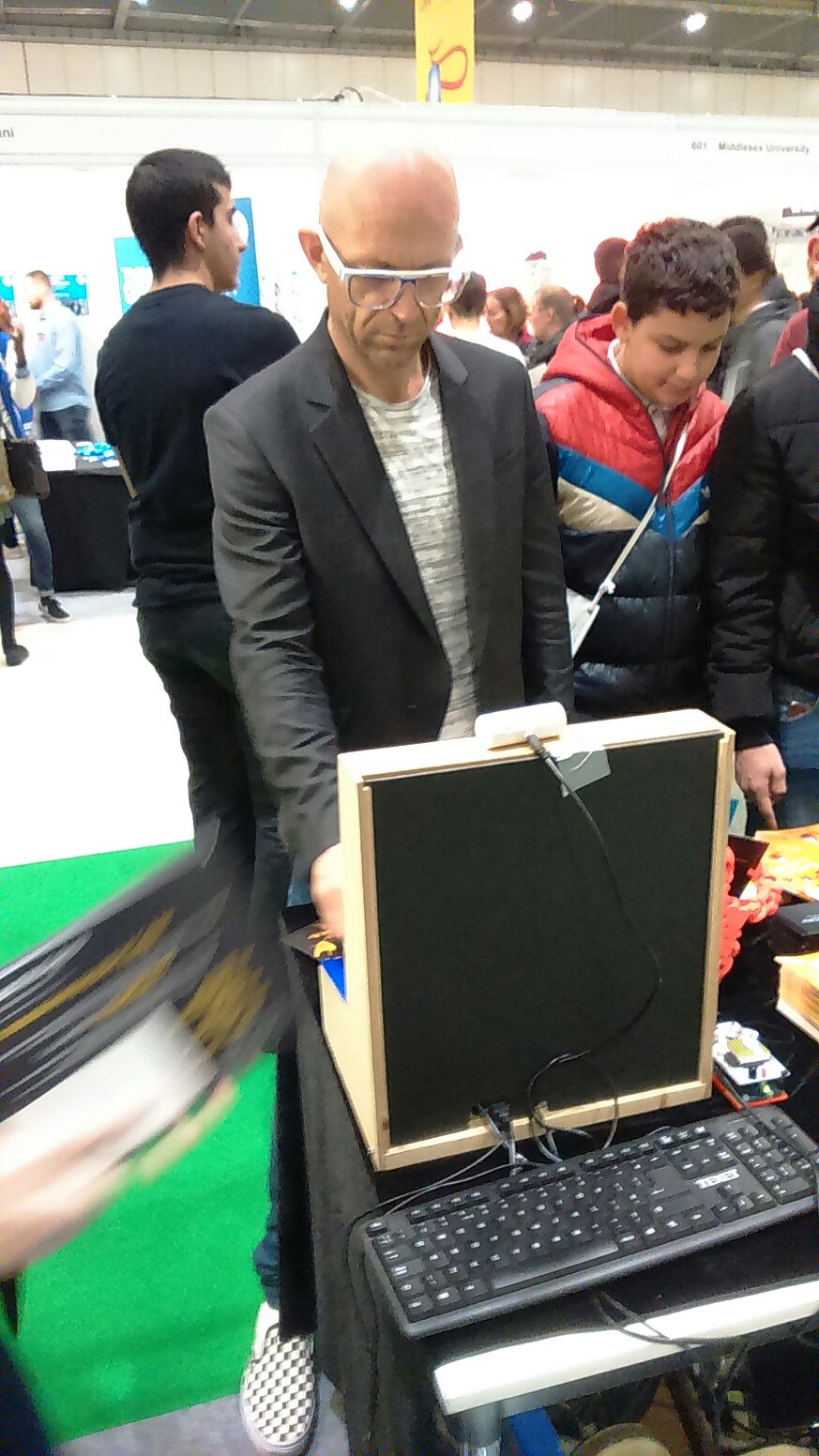
The three of us were very excited to see this project to completion. The arcade machine was very popular in the department, with students playing on it constantly. A few had build their computing projects on top of it.
Leveraging Generative Design in Design for Additive Manufacturing (DfAM)
A drum synthesizer panel made using an Arduino, Raspberry Pi, and an IKEA drawer.
A solid mechanics simulation made in Python
Turning a discarded SNES console turned into a capable Linux machine
Building a small arcade machine powered by a Raspberry Pi