Master’s Thesis
Leveraging Generative Design in Design for Additive Manufacturing (DfAM)
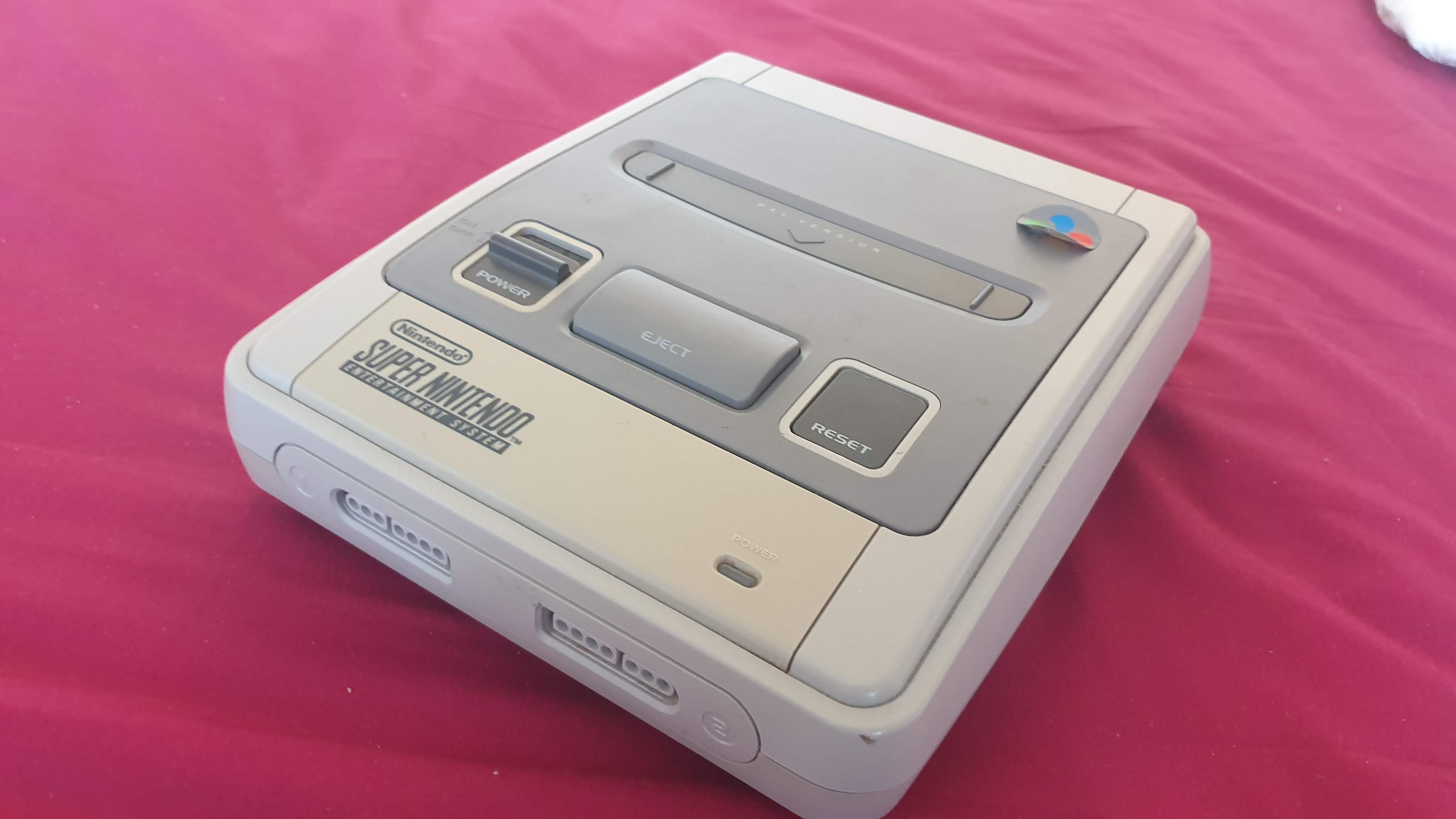
A while back, I was lucky enough to spot an old discarded SNES console with two working controllers at my local recycling centre.
Over the summer between sixth form and uni, I decided to turn it into something more modern and versatile.
I modified the internals so that there is now a Raspberry Pi inside. The controller ports are wired as inputs to the Pi, and can be configured to control anything as virtual game controllers or keyboard inputs.
On first inspection of the console, it was quite yellowed, smelled a lot, and the video out jack was very rusty. Other than this, the system seemed to be in good condition.
The console didn’t come with any wires and I didn’t have any games to test with it, so for a long time it was sitting inside a drawer.
Eventually, I bought a game and AV cable for the system. I powered the system with 9V DC using a buck converter to step down the voltage from a 12V DC I had lying around.
Fortunately, the console was in complete working order.
However, I didn’t want to start a collection of games. The system and controllers were in good condition, so I thought it could have been put to better use.
Looking underneath, I found that opening it up wasn’t as easy as picking up a screwdriver. The screws were a proprietary kind that Nintendo frequently used in its consoles called the ‘Game bit’.
I sourced the driver bit off Amazon and cracked open the console.
SNES opened up?
There were two things that I was looking for. Namely, where to install the Raspberry Pi, and how to connect the controller ports to it.
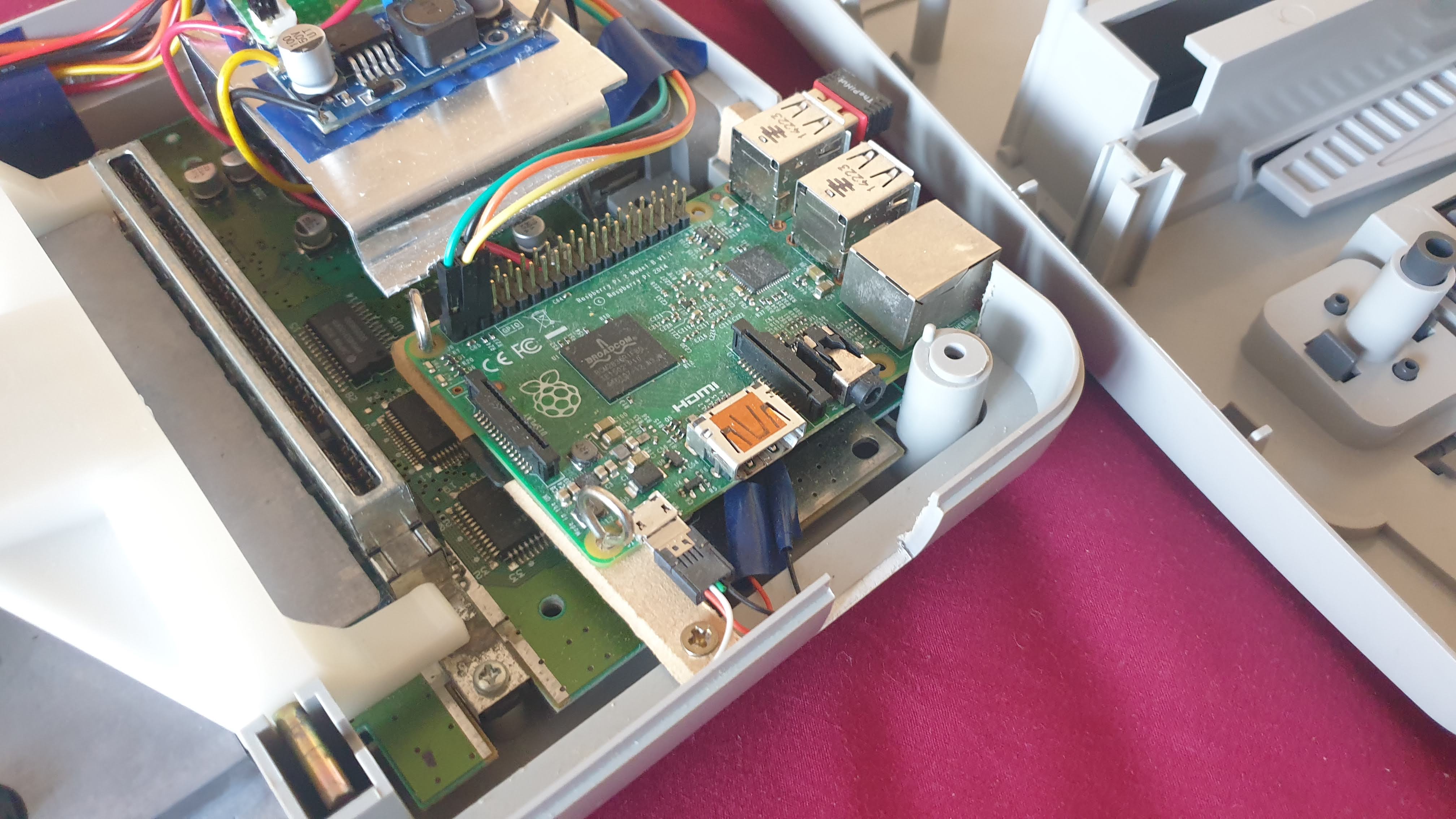
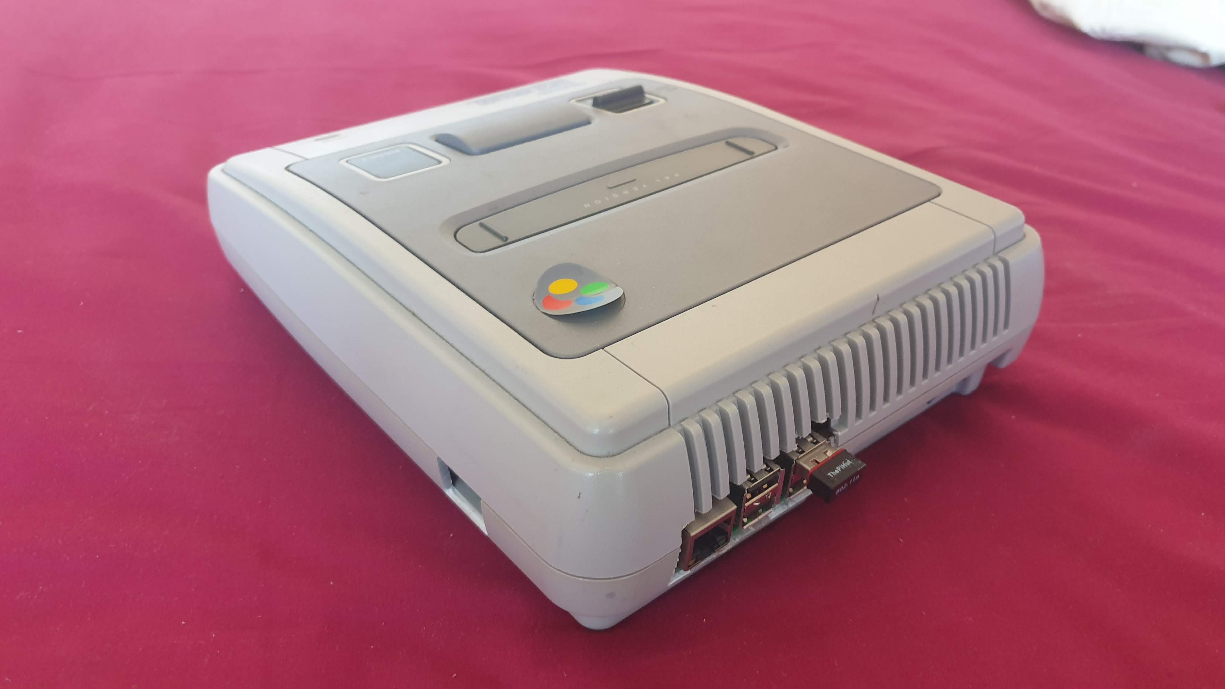
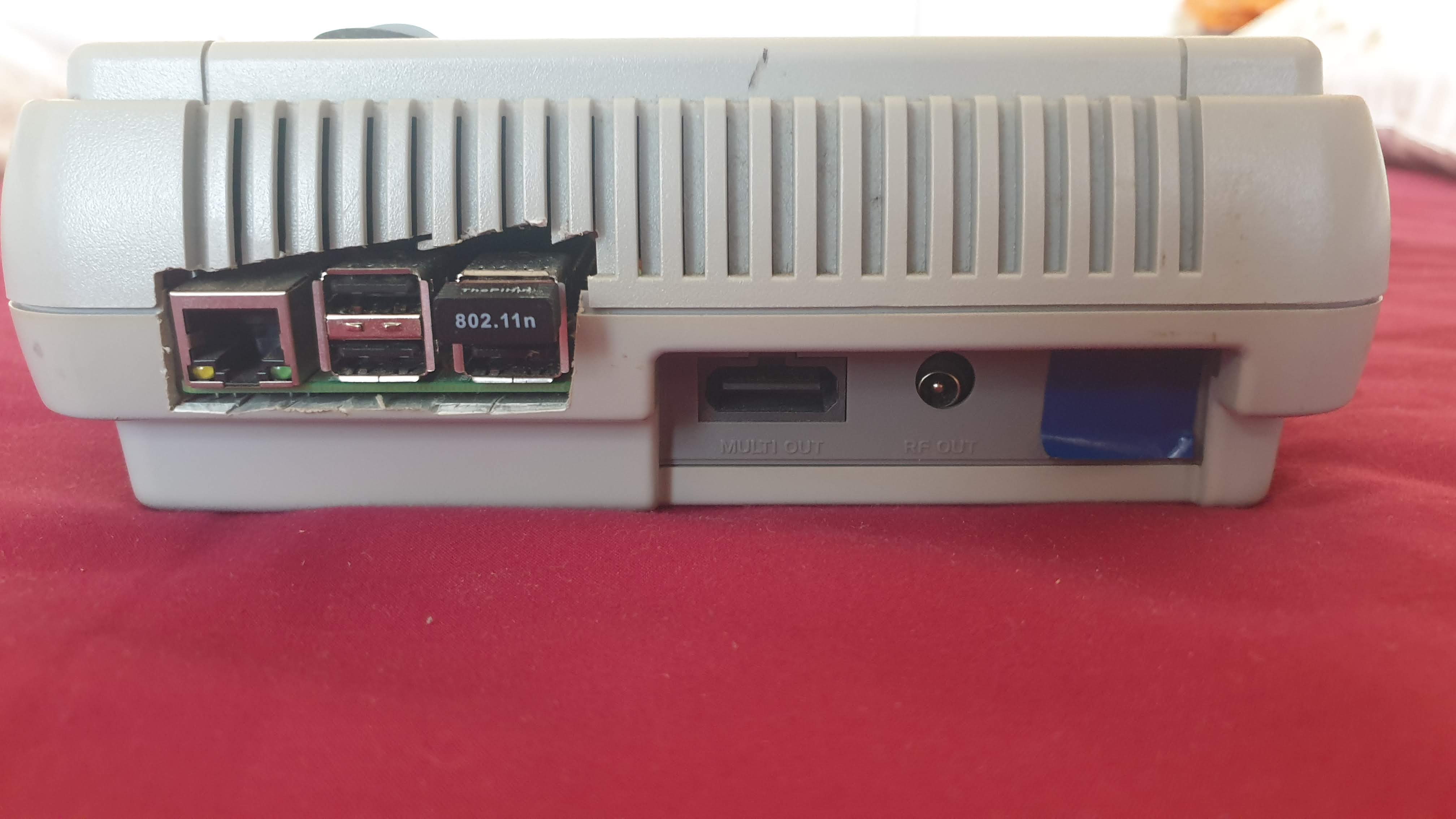
It was important to have easy access to the HDMI connector, therefore the right edge of the Pi needed to be on the side of the console. Access to the USB and Ethernet ports on the adjacent side were also desirable, so I decided to install the Pi in the top right corner.
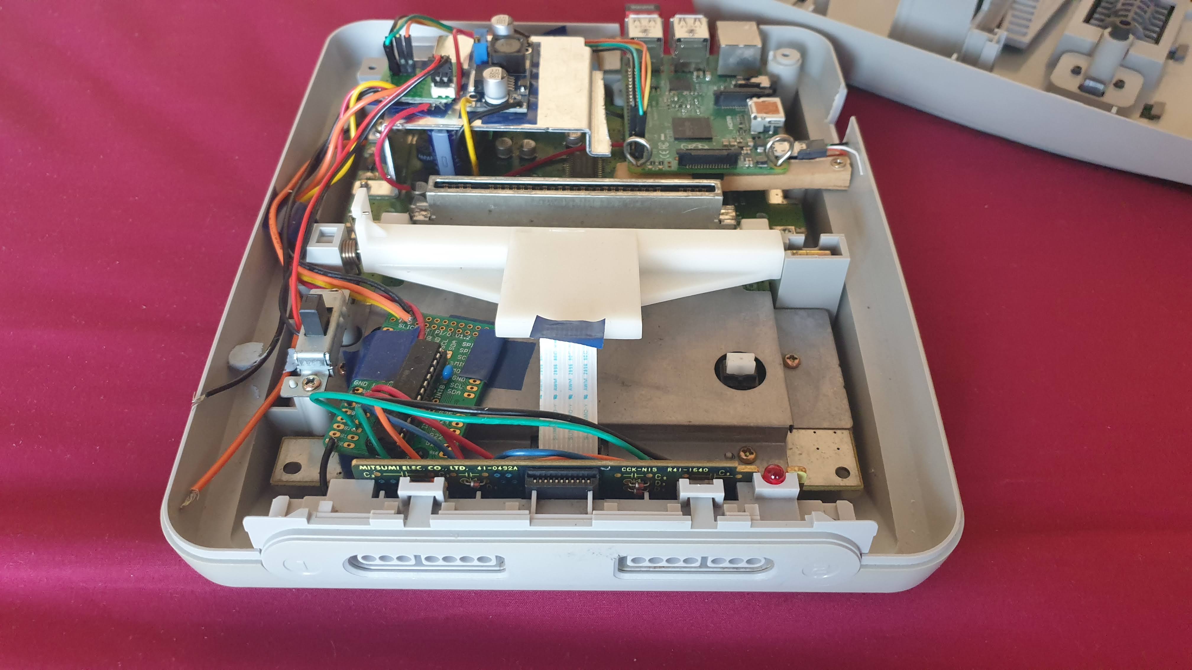
Pic showing Pi installed in corner
The SNES controllers communicate with the console via Clock, Latch, and Data signals. This system works by the reciever supplying a clock signal, then the controllers return whether buttons are pressed or not serially through the data signal.
Diagram showing how signals work?
I could’ve connected these lines to the Raspberry Pi GPIO pins, then acquired a driver to drive these signals. However, I opted to interface the signals using an intermediary chip.
The three controller signals are connected to GPIO pins on the MCP23017 GPIO expander chip. I had experience with this chip from my Arcade machine project so less time was needed for development. Additionally, the driver that I used in that project was also capable of handling SNES controller inputs.
I decided that it was best to install the Raspberry Pi in the top right corner of the system. There was some metal shielding in the way so I cut this off partially. I then screwed the Pi into the sides of the case.
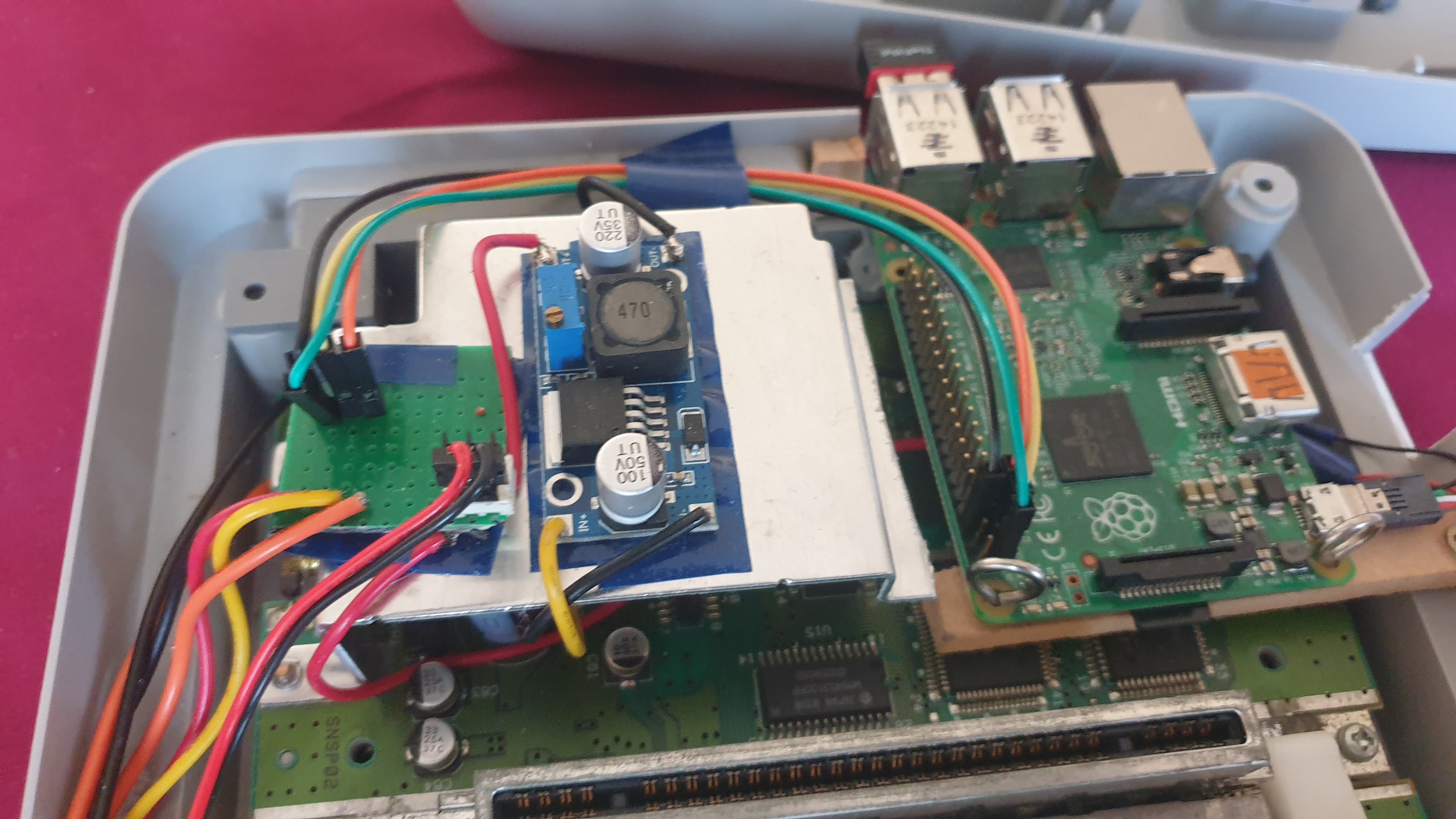
The Raspberry Pi needs 5V DC power to work. I wanted to power the system from a common 12V DC adapter, so I installed a buck converter.
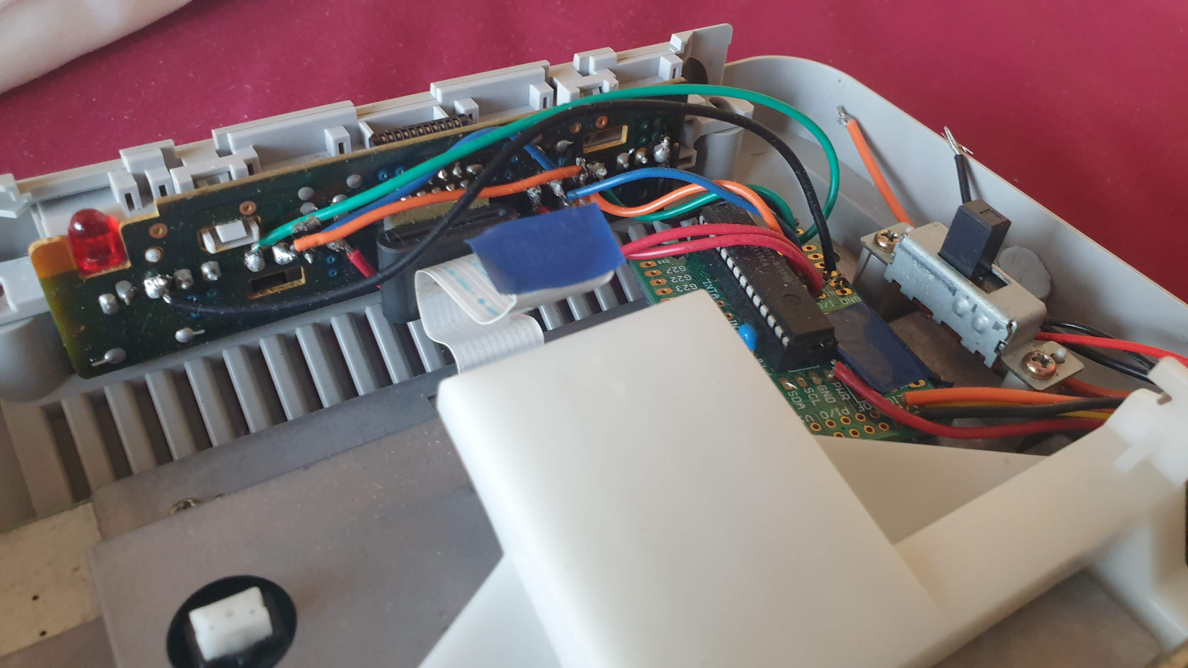
I also wanted the power switch in the case to actually turn on the Raspberry Pi. Fortunately, this wasn’t too difficult to do as it was easily disconnected from the SNES motherboard.
I cut a tiny piece of stripboard, and soldered some female headers to connect the switch. I then soldered on the wires from the DC power barrel. It is best to power the Pi using a Micro-USB cable, so I found a spare one lying around and soldered on the black and red leads.
Next, I needed to physically connect the controller ports to the Pi. I used the same MCP23017 breakout board from the Arcade Machine project. The Clock, Latch and Data signals were soldered to GPIO inputs for the chip, and the I2C bus lines were connected to the Raspberry Pi.
As with the Arcade Machine, I installed a Raspbian linux distro with RetroPie.
I also used the same modified driver used in the Arcade Machine that was written by petrockblog. The driver already had support for SNES controllers.
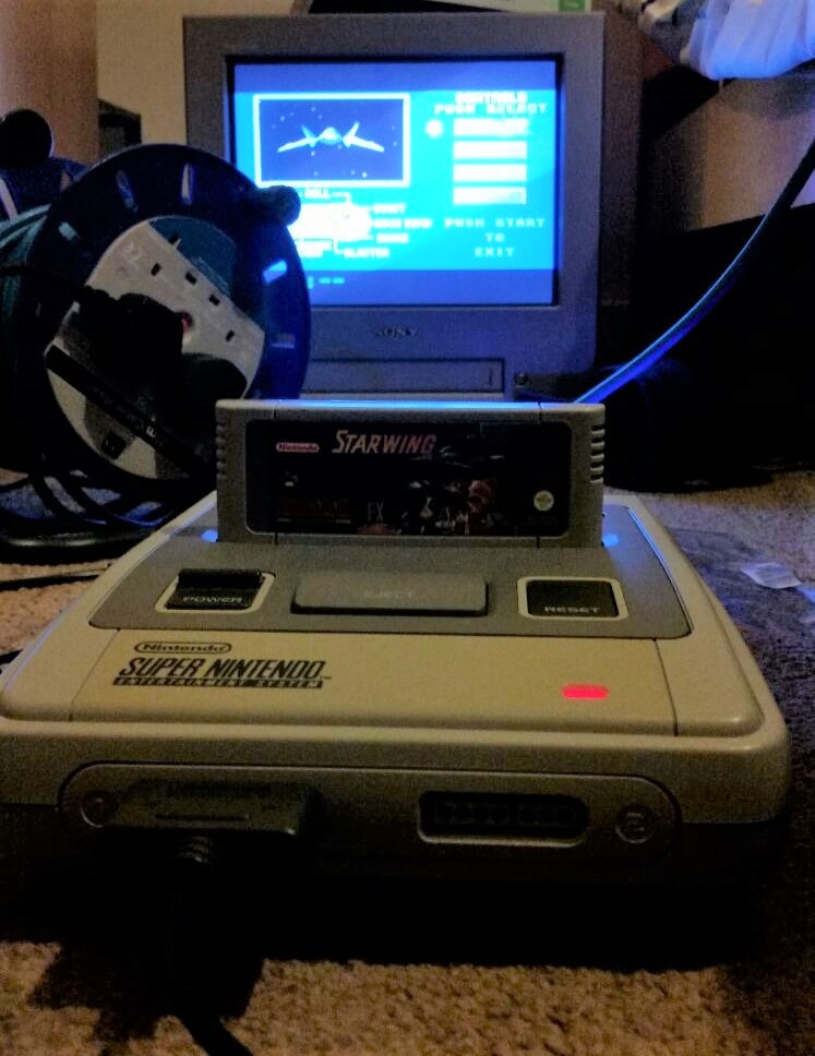
The finished product worked very well. The controllers were very responsive. Playing a range of Nintendo games and a few of my own was a pleasant experience with the controller.
Picture/clip of console being played?
Leveraging Generative Design in Design for Additive Manufacturing (DfAM)
A drum synthesizer panel made using an Arduino, Raspberry Pi, and an IKEA drawer.
A solid mechanics simulation made in Python
Turning a discarded SNES console turned into a capable Linux machine
Building a small arcade machine powered by a Raspberry Pi