Master’s Thesis
Leveraging Generative Design in Design for Additive Manufacturing (DfAM)
A project for making a custom MIDI instrument that is good for percussive music. I got inspiration for the idea from the Youtuber and artist LOOK MUM NO COMPUTER who produced a tutorial for an 8-step sequencer.
In his tutorial the core functionality was implemented using an Arduino Nano, but I extended it to handle an array of buttons, knobs, and LEDs to try and cover a wide array of use cases.
The layout for the panel was particularly inspired by the classic Roland TR-808 drum synthesizer.

These were the overall project goals
Below is an initial mock-up of how I envisioned the way these controls would be laid out. As mentioned above, the design mainly takes inspiration from the TR-808 drum machine.
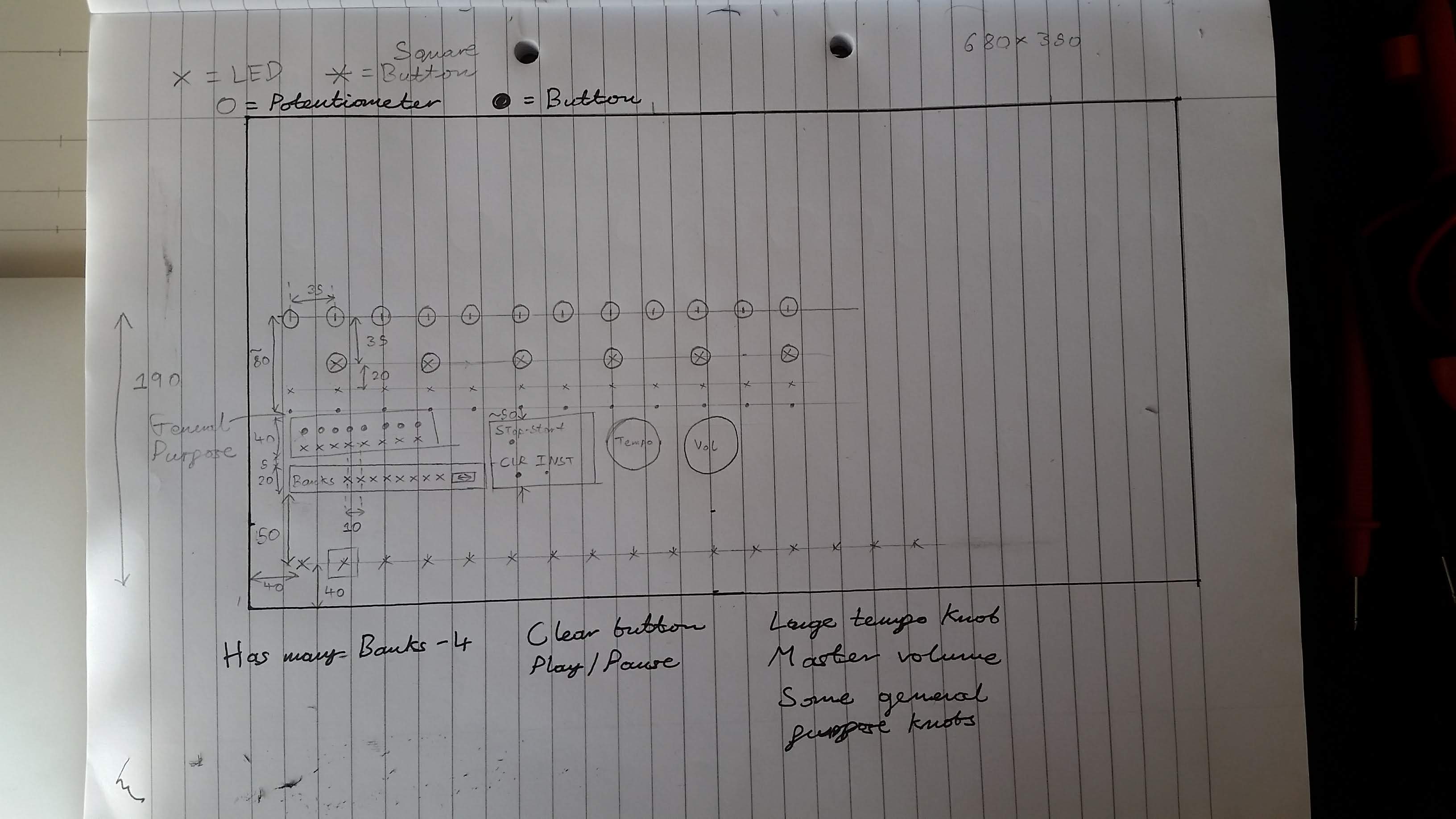
It was decided that the project needed to have the following controls:
The next step was to procure the hardware parts that would be suitable for this panel.
For the physical panel, I found an old IKEA drawer tucked up in my attic. This was perfect,
Some digging around was done on electronics suppliers like RS components and Rapid electronics, as well as eBay. The criteria was to find parts that suited the purpose well but were also inexpensive.
| Item | Description | Image | Dimensions | Interface |
|---|---|---|---|---|
| Instrument pad | Very tactile click. Fairly deep travel. | 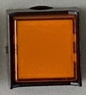 |
16mm x 16mm | 1 digital in |
| Channel knob | Small. High friction | 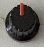 |
⌀ 10mm, depth 15mm | 1 analog in |
| Button | Tactile click. Little travel |  |
⌀ 2mm, depth 1mm | 1 digital in |
| Master knob | Large. Low friction |  |
⌀ 35mm, depth 15mm | 1 analog in |
| Master button | No tactility but deep travel | 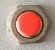 |
⌀ 7mm, depth 10mm | 1 digital in |
| Toggle switch | Tactile transition. Two-way throw |  |
⌀ 3mm, depth 10mm | 2 digital in |
| LED | 3mm and 5V. In red, yellow, green | 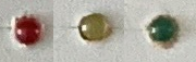 |
⌀ 3mm, depth 1mm | 1 digital out |
Taking inspiration from the 8 step sequencer project from LMNC, I decided to use a single Arduino Nano to handle all I/O, sequencing, signal processing and MIDI output.
A pair of rows of female headers were soldered to some stripboard to use as a socket for the Arduino. This stripboard was then placed in the corner of the box, next to where the wire sockets would be for power and MIDI out.
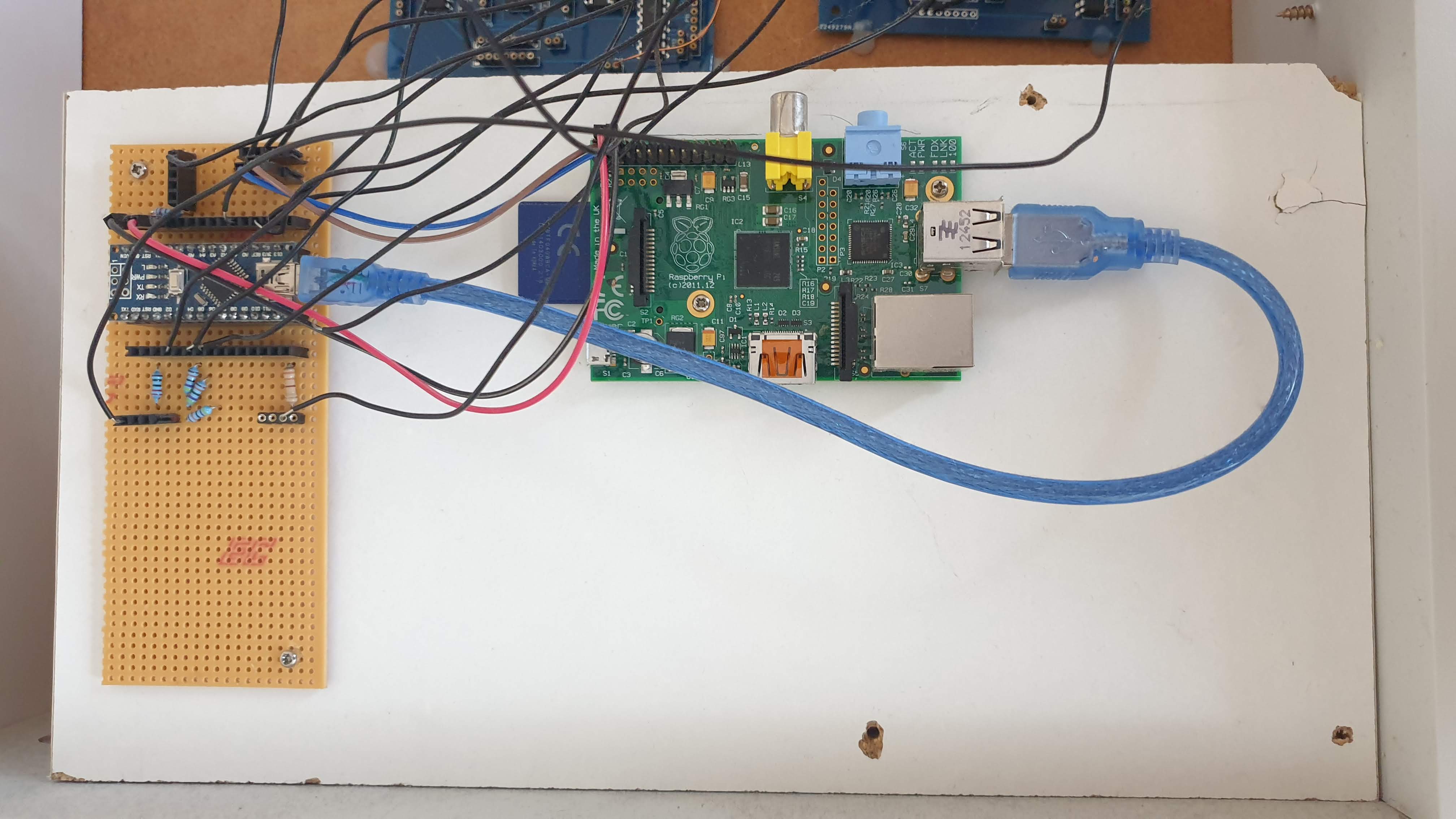
After doing the maths on all of the required hardware I/O ports required for all the knobs, buttons and LEDs, it became very clear that the Arduino’s 16 digital I/O and 6 analog I/O wouldn’t be adequate.
Table of hardware I/O with calculated number of required ports
As a result, some extra hardware was needed to provide additional ports.
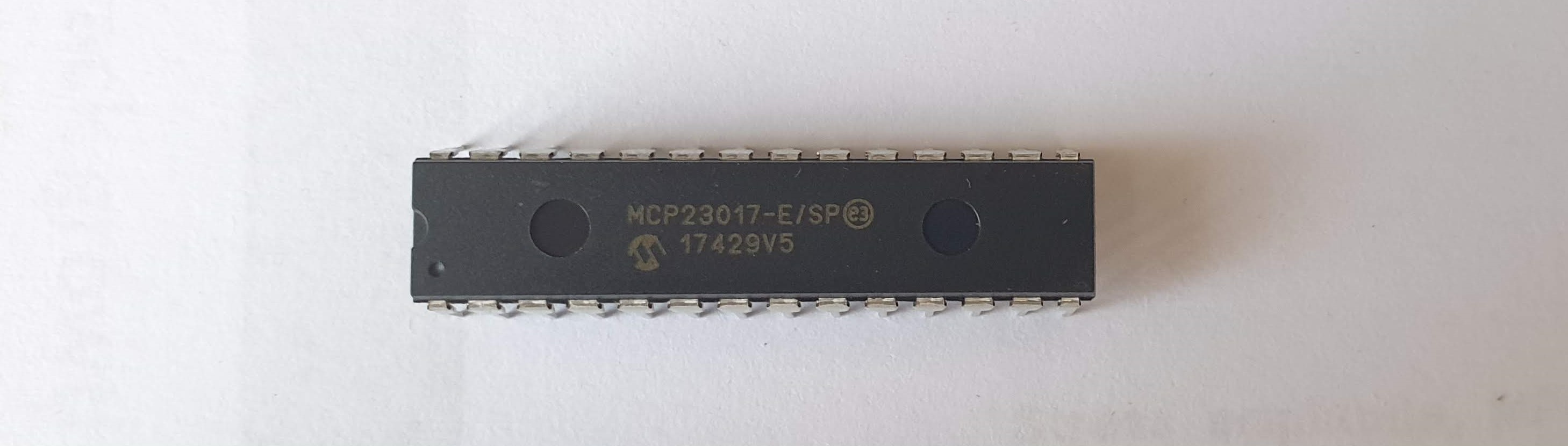
The MCP23017 I/O expander chip was used for providing additional digital I/O ports. Each chip provides 16 GPIO pins each with their own configurable pull-up resistors. The chip communicates via the I2C bus which is ubiquitous and widespread. This was also a desirable choice for this project because I had previous experience with using this chip for polling buttons and powering LEDs.
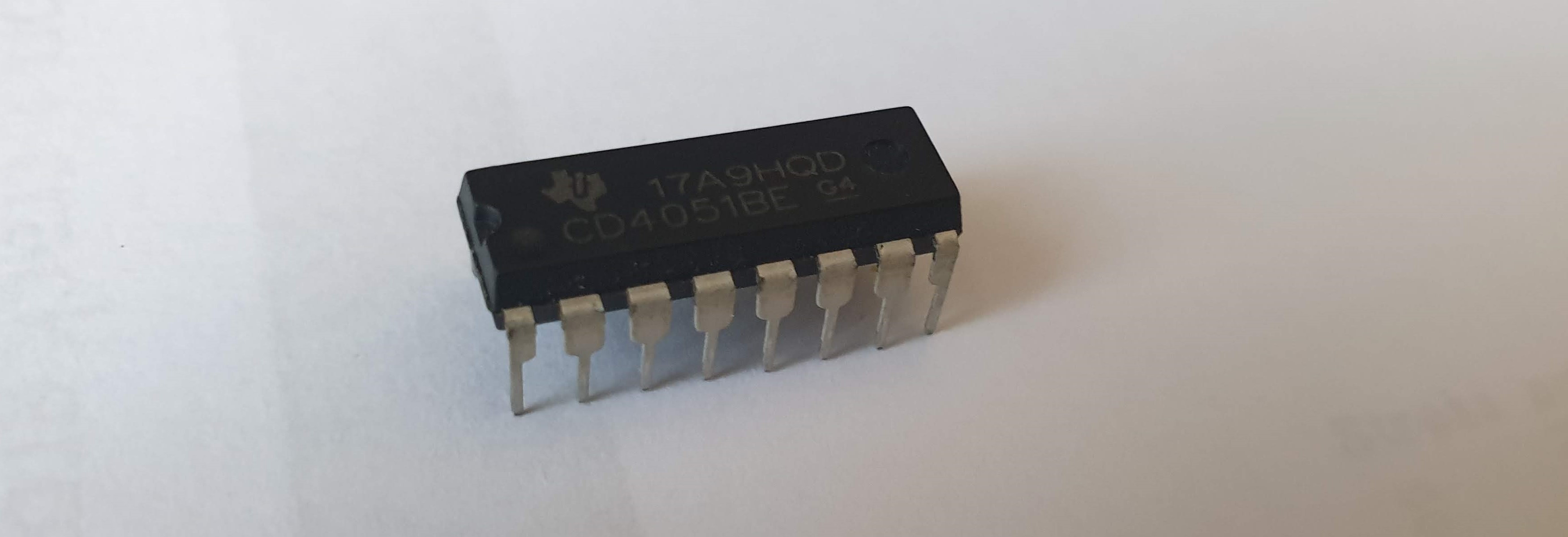
For additional analog inputs, the CD4015BE multiplexer chip was used. I decided to use this chip after seeing it in a few example sketches and projects for the Arduino. Using this chip was very simple. There are eight input pins which are multiplexed into a single output, with the input selected using three digital pins.
I was already quite familiar with the MCP23017 chip, so I went ahead and prototyped a piece of stripboard to accommodate eight of these chips, which happens to be the maximum number that can be used on a single I2C bus. Additionally, with eight chips there were 128 I/O ports which would be enough to accommodate all of the I/O with a few pins to spare.
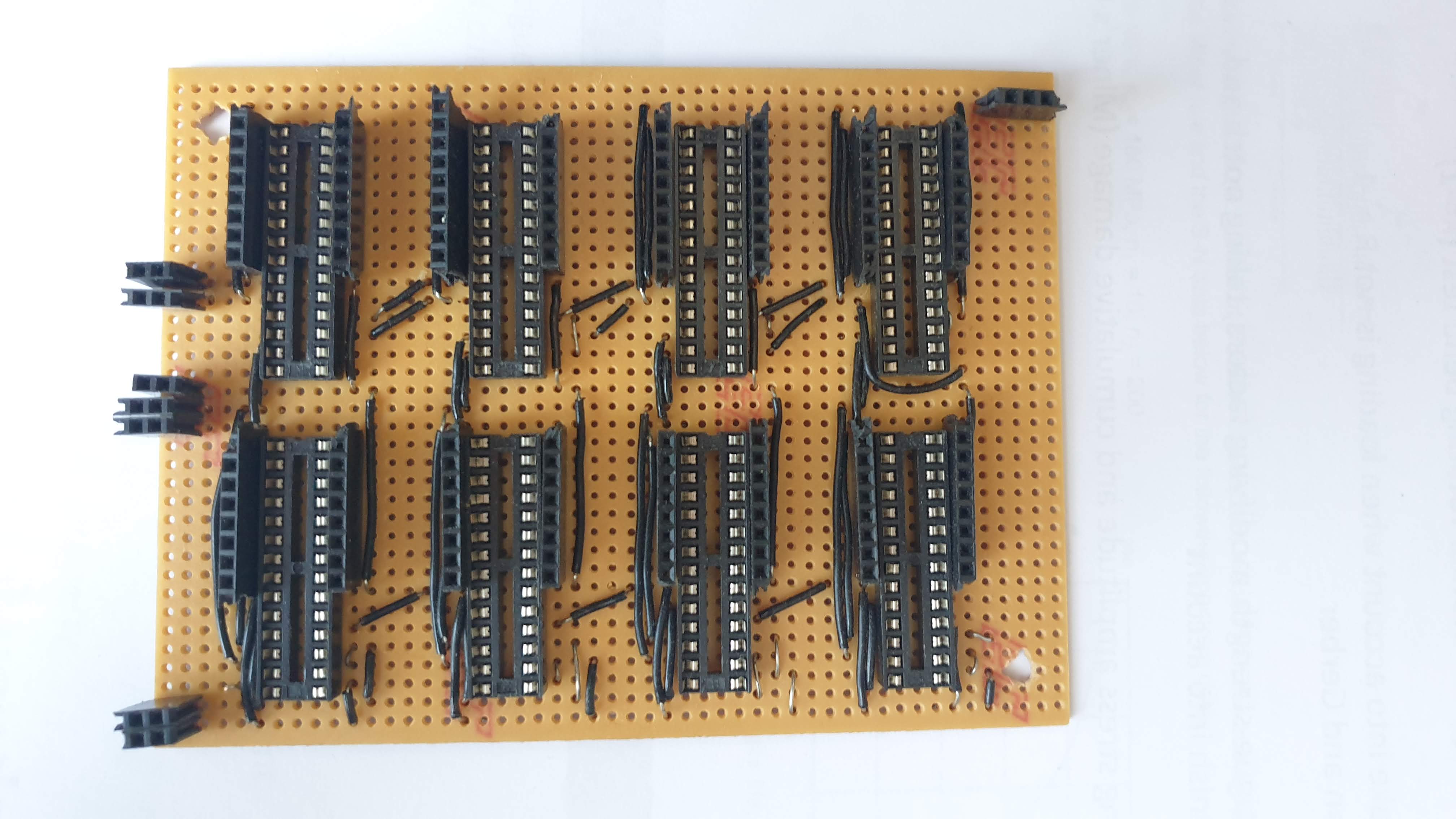
Each chip was hardwired with its own address ranging between 0 and 7. All of these chips were connected on common SDA and SCL bus lines.
Although I was very meticulous while making and soldering the board, there were many bugs present that caused intermittent problems. Some of the chips would have all of their GPIO fully functional and addressable, but others would be non-responsive or might even sporadically respond to different addresses. These intermittent problems were extremely irritating to troubleshoot, which led me to instead use manufactured PCBs as an alternative.
I used the online EasyEDA designer, which I picked up easily despite having little PCB design experience. There was also a good library of part footprints.
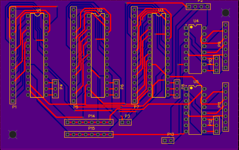
The only feasible option for manufacturing these PCBs was to have them manufactured from a batch service in China, which is most cost effective when ordered in large numbers. Because of this, I decided to try and make a board design that was as general as possible in the hope that they could be used in future projects.
Each board has space for three MCP23017 and two CD4051BE chips. This provides a total of 48 digital I/O pins and 16 analog pins per board.
Breakout holes were made for the GPIO and mux pins so that jumpers could be soldered. The address pins for each MCP chip are also exposed to allow for easy configuration. There are rows of 5V and GND lines at the bottom so that the user can easily solder wires to the address lines.
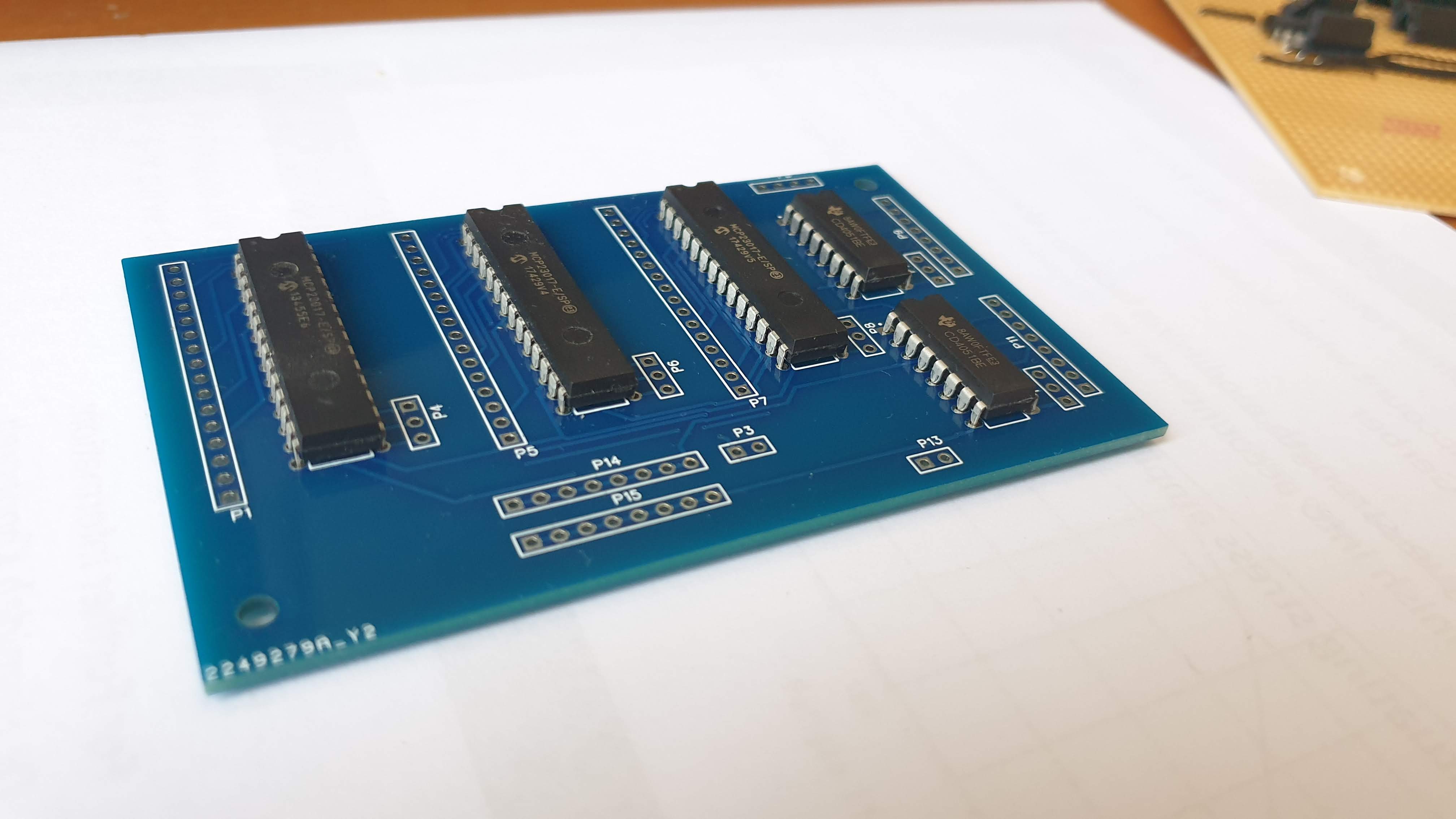
The result was much better than the stripboard prototype – all of the chips responded reliably to their assigned addresses and each GPIO pin worked fine.
The 21 analog inputs from the potentiometers were spread across the three CD4051BE multiplexer chips, with the selector bits controlled directly from the Arduino’s digital pins. The multiplexers worked exactly as expected, switching to the expected inputs as the selector bits were changed.
The Arduino ADC has a 10-bit resolution for 1024 discrete analogue values, which was too precise as the read values were quite unstable. Fortunately, when sending MIDI commands analogue values are represented by 7 bits or 128 discrete values so the instability disappears when these values are truncated.
I considered several solutions for connecting all of the hardware together. This was a daunting task as nearly 200 electrical connections needed to be made, which needed to be accessible and reliable.
These were some ideas that I considered:
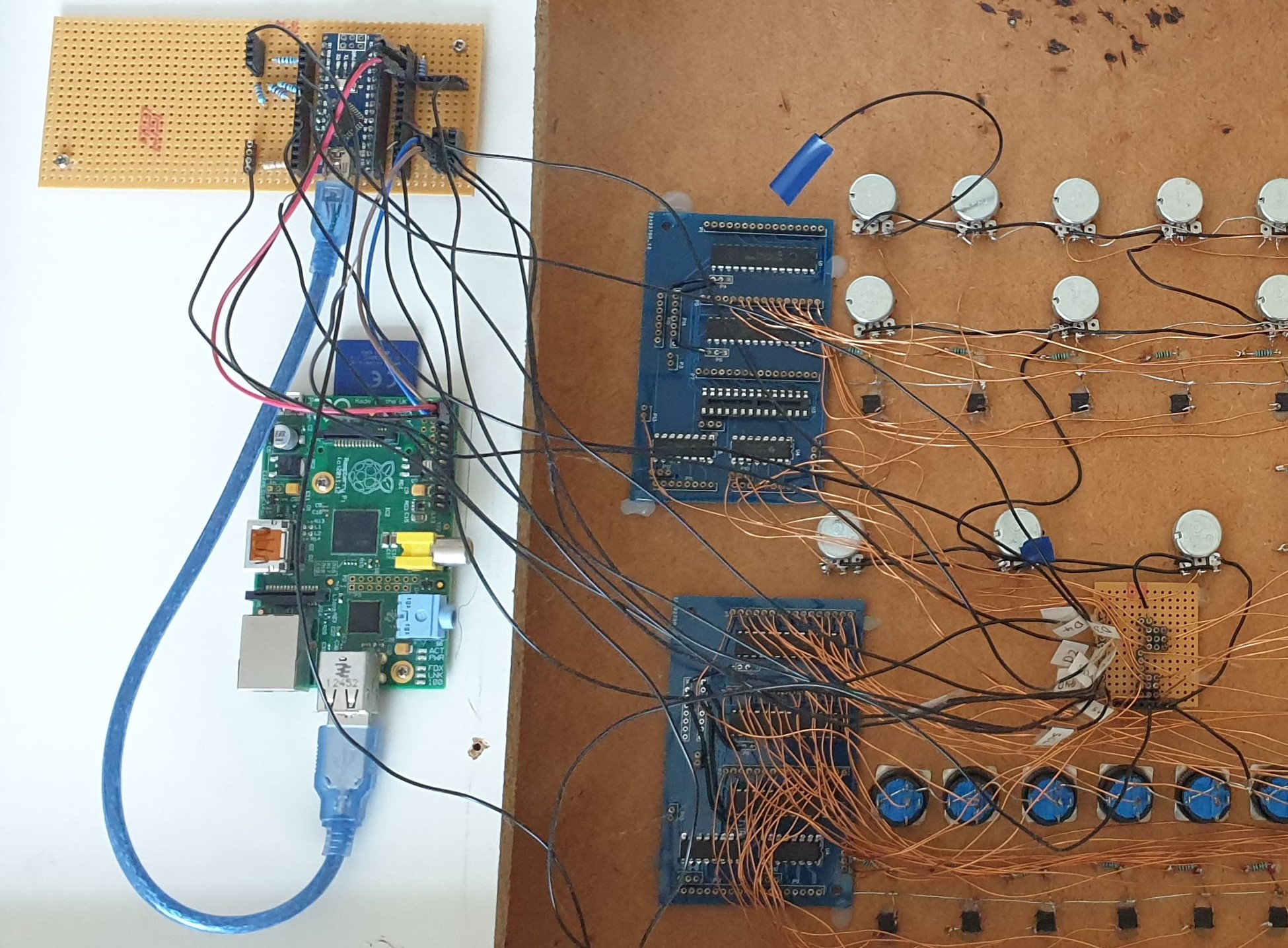
In the end I settled on using enamelled copper wire to connect everything together. The result was positive - connections were very reliable, and cable management was easy.
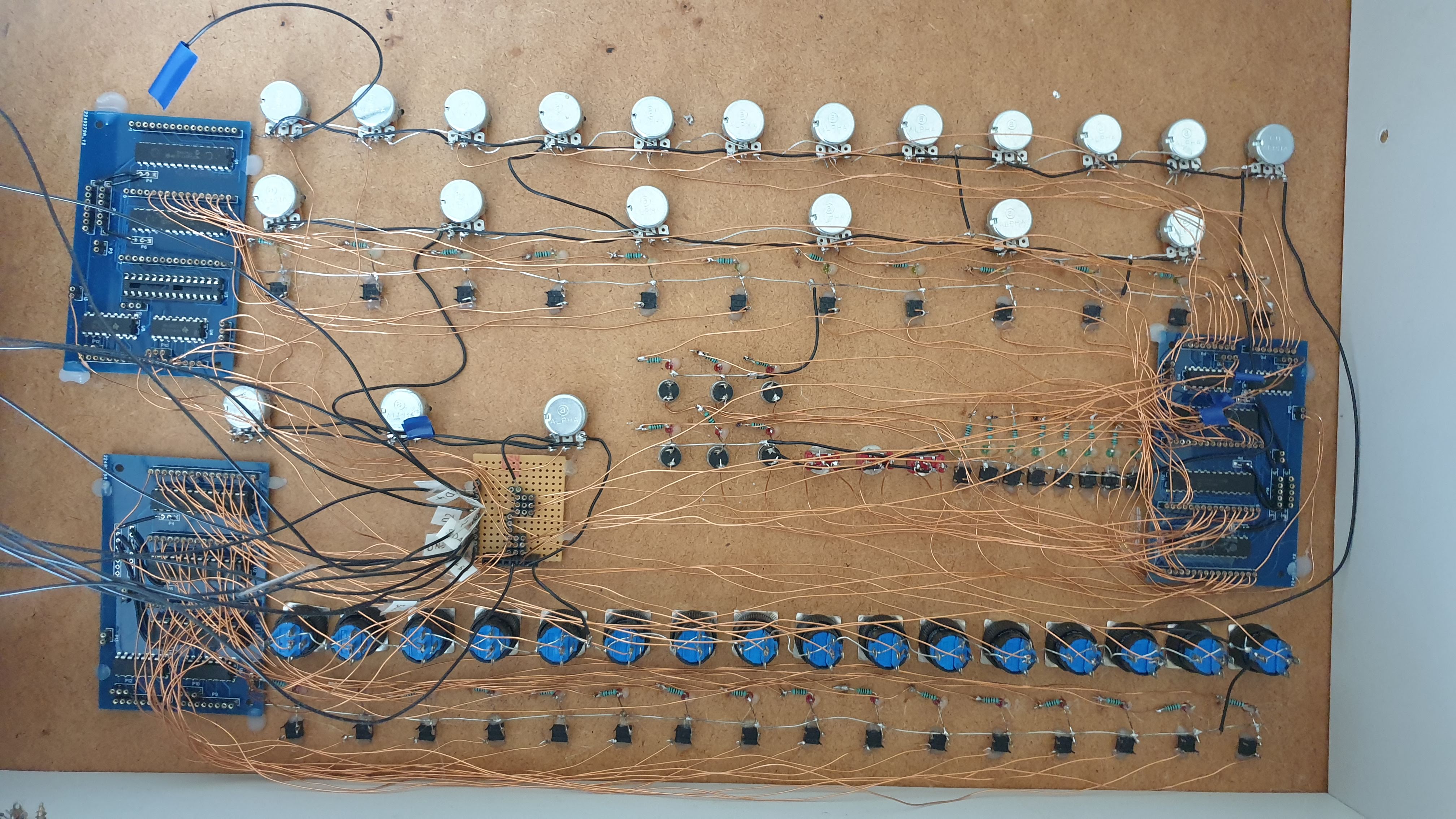
Once all the hardware was connected to the multiplexer PCBs, everything could be controlled using just twelve electrical connections. These were connected to the Arduino/Raspberry Pi controller.
To test and debug the individual buttons, knobs and LEDs, I made a graphical testing app that draws a representation of the panel and indicates when a button is pressed, an LED is on and when a knob is turned on.
Screenshot/animation of diagnostics app
Additionally, to calibrate and test the knobs, I made another applet that graphs the outputs of the analogue knobs, giving the user the option to select the address and analogue input.
Screenshot/animation of knob testing app
Next, I made a simple app that sends MIDI notes to the MIDI out port if the user presses one of the instrument pads. I connected the box to my Mac running Logic Pro with a MIDI cable, and notes were played successfully.
This program was extended into a simple 16 step sequencer. The panel plays the instrument LEDs in a regular 16-step beat. When the user presses an instrument pad on a certain beat, it is recorded into a small ‘memory bank’ and that instrument will be played on that beat.
Recording of panel flashing LEDs in sequence?
Animation of LEDs flashing individually
Leveraging Generative Design in Design for Additive Manufacturing (DfAM)
A drum synthesizer panel made using an Arduino, Raspberry Pi, and an IKEA drawer.
A solid mechanics simulation made in Python
Turning a discarded SNES console turned into a capable Linux machine
Building a small arcade machine powered by a Raspberry Pi